| [ TECHNICAL HOME ] | [ RAILROAD HOME ] | ||
|
by Steve Sconfienza, Ph.D. |
The GG1 and AC Motors
Doing the Math
The GG1 utilized 12 six-pole motors (GEA-627-A1), 400 volts at 25 Hz. Each motor was rated at 385 hp, with the 12 motors mounted in pairs over each of the six driving axles. Each motor was geared to what is called a "quill," a shroud around the axle itself, and the quill was connected to the drivers themselves by means of spring and cup arrangement. The motors themselves were mounted on the frame, providing a flexible suspension system: this allowed essentially full and equal traction for each of the drivers regardless of track condition. (There are several sites with diagrams and photos of the GG1, its transformer, motors, and quill drive: see, for example, www.steamlocomotive.com's GG1 page and from The American Society of Mechanical Engineers their GG1 brochure and landmark page.)
These notes on the GG1 started as a simple example of how AC motors work: known quantities (AC frequency, size of drivers, gearing) equal known quantities speed of locomotive). However, the GG1 turned out to be a bad example of modern AC traction, in that it does not use modern AC traction, so to speak: it did not work out as an AC induction motor. Unfortunately, there is not a lot of technical information on the motors themselves. There are plenty of photographs and diagrams of the locomotove and there are photographs of the motors, but as of the date this was prepared (originally in early 2003, but subsequently revised through late 2004), no wiring diagrams or even general descriptions of the motor internals has surfaced. So, this required a bit of detective work (more so than just being a historian).
Here is what happened as I researched the motors (skip ahead to the punchline):
- First, the givens,
- The GG1 had passenger gearing of 24/77 and was rated for 100 miles per hour (freights were 22/79 for 90 mph).
- The GG1 had 57" diameter drivers.
- The GG1 had six-pole motors.
- The electrical supply was 25 cycle AC (i.e., 25 Hz) at 11,000 volts.
- Next, some calculations,
- A 57" driver has a circumference of 179.07 inches (thus it will travel 179.07 inches per revolution, about 15 feet).
- A 25Hz, six-pole induction motor has approximately a 480 rpm full load speed:
- 25 Hz / (6/2) [i.e., poles/2] = 8 1/3 * 60 [seconds per minute]= 500 * .96 [efficiency factor] = 480 rpm.
- 480 rpm with a 24/77 reduction gear produces 137 rpm.
- 179.07 inches per revolution * 137 revolutions per minute = 23.23 miles per hour
- 179.07 inches per revolution * 137 revolutions per minute = 24,532.59 inches per minute (about 2,044 feet per minute)
- 24,532.59 inches per minute = 1,471,955.4 inches per hour
- 1,471,955.4 inches per hour = 122,662.95 feet per hour
- 122,662.95 feet per hour = 23.23 miles per hour
- A 57" driver would need to turn at 589.71 rpm to make 100 mph.
- 100 miles per hour * (5280 feet per mile * 12 inches per foot) =
- 6,336,000 inches per hour, which equals 105,600 inches per minute.
- 105,600 inches per minute / 179.07 inches per revolution = 589.71 revolutions per minute.
- 589.71 rpm @ 24:77 gearing = 1891.99 rpm at the motor.
That does not work as an induction motor: 1892 rpm required at the motor (step 6) versus 480 rpm computed for this motor (step 2).
- Other options?
-
Power control on the GG1 was through a "Tap Changer": there was no motor/generator or other means of
chaning the 25 cycle AC to anything else. If the tap changer on GG1 transformer were to have had taps
that cycled through the pole pairs on the motors as well as through the transformer windings (cycling
through the transformer windings varies the output voltage of the transformer), and it finally got to
two poles, this would have approximately a 1440 rpm full load speed (it is unlikely that an AC motor
would do this due to the nature of the motor windings, but as noted elsewhere, it would not have
been impossible):
- 25 Hz / (2/2) = 25 * 60 = 1500 rpm * .96 = 1440 rpm.
- But 1440 rpm @ 24:77 gearing is still short:
- 1440 rpm * (24/77) = 449 rpm.
- 179.07 inches per revolution @ 451.95 rpm = 80,402 inches per minute.
- 80,402 in/min = 4,824,145 in/hr = 402,012 ft/hr = 76 mph.
So anyway, that's not right, either.
-
Power control on the GG1 was through a "Tap Changer": there was no motor/generator or other means of
chaning the 25 cycle AC to anything else. If the tap changer on GG1 transformer were to have had taps
that cycled through the pole pairs on the motors as well as through the transformer windings (cycling
through the transformer windings varies the output voltage of the transformer), and it finally got to
two poles, this would have approximately a 1440 rpm full load speed (it is unlikely that an AC motor
would do this due to the nature of the motor windings, but as noted elsewhere, it would not have
been impossible):
Here was the detective work. Although all the math is obvious, this comes out not even close. From the number of different resources, it appears clear that speed, gearing, and size of the drivers is correct. It was 25 cycle AC. It is also evident that the number of poles for the motors is correct, although there are fewer clearly indpendent resources that can be used to confirm that (nothing says anything but six poles). Given that, the fastest that an induction motor could turn was is 480 rpm (just for now forgetting the possibility of the 1450 rpm with the transformer taps changing the feed to the windings on the stator). Working backward from the 57 inch driver moving at 100 mph, the axle had to be turning at about 590 rpm, and with the 24:77 gearing that means the motor shaft had to be turning at about 1900 rpm. It has been noted elsewhere that the locomotive tested at 110 mph, which gives an axle rotation of nearly 650 rpm and a motor shaft rotation of 2085 rpm; so, the synchronous speed of this motor would have to be at least 2100 rpm. Unfortunately, a 25 cycle AC induction motor cannot turn at 2100 rpm: the rotor cannot turn at anything over 1500 rpm under any circumstances. There is something else happening here.
A fairly simple spreadsheet presents these relationships (as if the GG1 were to have had
induction motors) at the end of this page (go to the tables).
The GG1 Without All the Math
There is a six pole AC motor that will operate at 2100 rpm: a "universal motor." A universal motor can operate on either AC or DC (see AC Motors and the motors graphic).
The rotor has coils that are connected to the external circuit through a commutator on the shaft. The electrical field in the rotor will oppose the electrical field in the stator at any given moment, regardless of whether or not the polarity of the supply current changes with time. With DC, a DC field in the rotor will always oppose a DC field in the stator in the same direction; with AC, as the AC cycle alternates, it will alternate identically in the rotor and the stator, so there too there will always be opposition.
Universal motors may operate a high speeds regardless of the supply frequency, up to 10,000 to 20,000 rpm. They characteristically have high power-to-weight and power-to-size ratios and high starting torque.
Here are the actual GG1 numbers: the speed of the motor is limited by the load on the motor (i.e., the weight of the train). The transformer taps vary the voltage applied to the motor, with increased voltage driving increased current through the load on the circuit (i.e., the motor) and driving the motor at a higher speed.
Table One: Universal Motor Examples
| entered values ==> | computed values ==> | given | |||||||||||||
| Drivers | Motors | Gearing | Motor Speed |
Axle Speed |
Travel | ||||||||||
| diameter | AC freq | poles | ratio | reduction | |||||||||||
| (inches) | (cps) | (rpm) | (rpm) | (in/min) | (in/hr) | (ft/min) | (ft/hr) | (mph) | |||||||
| As Specified: | |||||||||||||||
|---|---|---|---|---|---|---|---|---|---|---|---|---|---|---|---|
| - - pass.(1) | 57 | 25 | 6 | 24 : 77 | 0.311688 | 1891.99 | 589.711 | 105,600 | 6,336,000 | 8,800 | 528,000 | 100.00 | |||
| - - pass.(2) | 57 | 25 | 6 | 24 : 77 | 0.311688 | 2081.19 | 648.682 | 116,160 | 6,969,000 | 9,680 | 580,800 | 110.00 | |||
| - - freight | 57 | 25 | 6 | 22 : 79 | 0.278481 | 1905.84 | 530.739 | 95,040 | 5,702,400 | 7,920 | 475,200 | 90.00 | |||
| Notes: |
(1) Passenger Design Speed
(2) Passenger Test
Speed
|
||||||||||||||
Table Two: Hypothetical Induction Motor Examples
NOT the GG1
| entered values ==> | computed values ==> | ||||||||||||||||
| Drivers | Motors | Gearing | Axle Speed |
Travel | ERROR | ||||||||||||
| (*) | diameter | AC freq | poles | slip | speed | ratio | reduction | % of actual |
multiple required |
||||||||
| (inches) | (cps) | (1-slip) | (rpm) | (n:1) | (rpm) | (in/min) | (in/hr) | (ft/min) | (ft/hr) | (mph) | |||||||
| As Specified: | |||||||||||||||||
| -- passenger | 57 | 25 | 6 | 0.96 | 480 | 24 : 77 | 0.311688 | 149.61 | 26,790.85 | 1,607,450.96 | 2,232.57 | 133,954.25 | 25.37 | 25.37% | 3.941644 | ||
| -- freight | 57 | 25 | 6 | 0.96 | 480 | 22 : 79 | 0.278481 | 133.67 | 23,936.55 | 1,436,193.00 | 1,994.71 | 119,682.75 | 22.67 | 25.19% | 3.970497 | ||
| Changing Poles: | |||||||||||||||||
| -- 4 poles | 57 | 25 | 4 | 0.96 | 720 | 24 : 77 | 0.311688 | 224.42 | 40,186.27 | 2,411,176.44 | 3,348.86 | 200,931.37 | 38.06 | 42.28% | 2.627763 | ||
| -- 2 poles | 57 | 25 | 2 | 0.96 | 1440 | 24 : 77 | 0.311688 | 448.83 | 80,372.55 | 4,822,352.88 | 6,697.71 | 401,862.74 | 76.11 | 76.11% | 1.313881 | ||
| Less Slip: | |||||||||||||||||
| -- 6 poles | 57 | 25 | 6 | 0.99 | 495 | 24 : 77 | 0.311688 | 154.29 | 27,628.06 | 1,657,683.80 | 2,302.34 | 138,140.32 | 26.16 | 26.16% | 3.822201 | ||
| -- 2 poles | 57 | 25 | 2 | 0.99 | 1485 | 24 : 77 | 0.311688 | 462.86 | 82,884.19 | 4,973,051.41 | 6,907.02 | 414,420.95 | 78.49 | 78.49% | 1.274067 | ||
| No Slip Speeds: | |||||||||||||||||
| -- 2 poles | 25 | 2 | 1.00 | 1500 | |||||||||||||
| -- 4 poles | 25 | 4 | 1.00 | 750 | |||||||||||||
| -- 6 poles | 25 | 6 | 1.00 | 500 | |||||||||||||
| Working Backward | |||||||||||||||||
| fixed values ==> | <== computed values | (simple conversions of entered speed) | (mph) | ||||||||||||||
| -- 100 mph | 57 | 25 | 6 | 0.96 | 1892 | 24 : 77 | 0.311688 | 589.711 | 105,600 | 6,336,000 | 8,800 | 528,000 | 100.00 | ||||
| -- 110 mph | 57 | 25 | 6 | 0.96 | 2081 | 24 : 77 | 0.311688 | 648.682 | 116,160 | 6,969,000 | 9,680 | 580,800 | 110.00 | ||||
| 2085 | 24 : 77 | 0.311688 | 650 | ||||||||||||||
| Notes: |
red= known values
|
||||||||||||||||
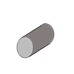
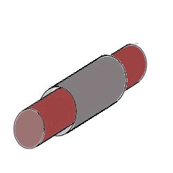
The GG1 Quill Drive
This is pretty much irrelevant in terms of the AC motors themselves, but some people find this a difficult concept to grasp (and I did at first, too). Perhaps the following diagrams will help with the visualization process.
The Basic Quill:
A Hollow Tube
The Quill with an Axle
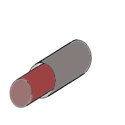
The axle passes through the hollow quill.
The Quill with an Axle: Fully Transversing
The Quill with Mounted Motors
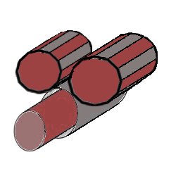
The motors sit on top of the quill.
Motors with DriveShafts

The drive shafts are parallel to the axle/quill assembly.
Drive wheels with drive gears
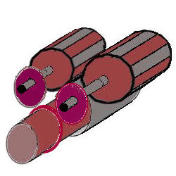
The drive shafts each connect to one small gear that both drive a single large gear connected to the wheel.
A Different Approach: The Milwaukee Road's "Bipolar" Electric Locomotives

A different approach to a high-speed electric passenger locomotive was followed by the Milwaukee Road (CMStP&P). Classified as an express passenger locomotive, the Milwaukee "Bipolar" -- developed by General Electric -- was so-named because of its motor: the bipolar utilized two-pole DC motors. The unit utilized a total of 12 of these motors, each of which was rated at 370 horsepower and was gearless. The feed to the locomotive was 3,000 volts DC fed via overhead catenary. A few other specifications are as follows:
Table Three: Milwaukee Bipolar
| Weight: | 457,000 lbs |
| Adhesion: | 530,000 lbs |
| Max. Axleload: | 38,500 lbs |
| Overall Length: | 76ft 0in |
| Tractive Effort: | 123,500 lbs |
| Max. Speed: | 70 mph |
| Horse Power: | 4,020 hp. |
References and Credits
GG1 technical specifications from www.steamlocomotive.com (The Pennsylvania Railroad GG1) and from The American Society of Mechanical Engineers (Pennsylvania Railroad GG1 Electric Locomotive #4800); general diagrams of various incarnations of the GG1 may be found at Rob's Pennsy home page (PRR Electric Locomotive diagrams). Bipolar locomotive graphic courtesy of Media by McCann ("Inside the Roundhouse"); technical specificaions from Chris Ashmore, Transportation Artist.
| revised 6 March 2012 | Go to Railroad home page | [ TOP ] |