Tim’s Powerstroke Intercooler and Electric Fuel Pump
Installation Page
(Updated October 2006)
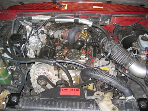
Before Intercooler:
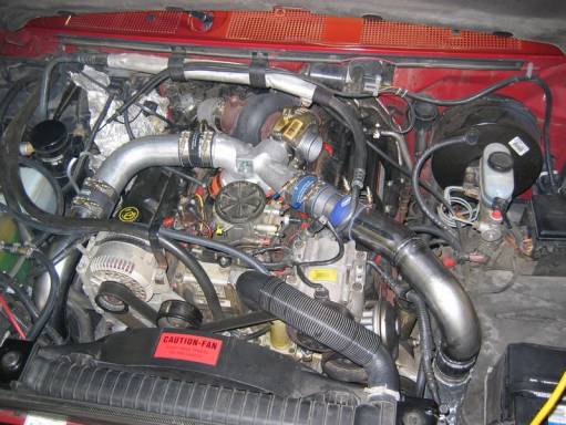
After Intercooler:
Installing
a ‘99+ Super Duty I/C in a ‘94-‘97 F-Series truck:
Let me start by stating that there is very little original information contained in this page. I share this in hopes that the photos and tips will make the job easier for someone. Many of the ideas I utilized came from Kevin Ferguson’s intercooler (I/C) installation as well as Geoff Thomas’ installation method. The pipe routing is roughly modeled after the path Geoff’s pipe kit takes. The idea of mounting the intercooler higher than Geoff does to avoid cutting any of the double thick section of sheet metal on the lower corners of the radiator support came from Kevin’s installation.
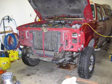
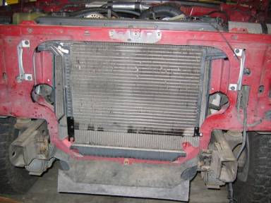
Here is where I started, after removing the front sheet metal parts outlined in Geoff’s write up.
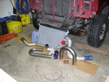
Parts - These are the basic parts utilized in my installation. The factory Super Duty pipes pictured were cut and spliced with sections of the 3” diameter mandrel bent 18-gauge Hooker exhaust tubing I purchase from Summit Racing. The “J” bend has a 4” radius bend, whereas the “U” bend is a larger 6” radius bend. The intercooler itself is an aluminum tank Super Duty part (a takeoff part from a Bank’s installation) and the Y-pipe is an Early ‘99 part purchased new from my local Ford dealer. The overall cost of these installations really hinges on how good of a deal you get on the I/C itself. I was fortunate enough to have a friend in Sandy, OR who was able to snag mine, with factory pipes, couplers, and clamps for $100 (Thanks Jimmie!). I made each pipe in two sections and joined them with the black and blue silicon couplers seen in front of the Y-pipe. I purchased the couplers from hosetechniques.com and they are three-ply, .140” thick, Aramid fiber reinforced pieces. Their color options allowed me to maintain Ford’s color-coding of blue on the hot side ducting and black on the cold side. The best price I found on constant torque, floating bridge clamps (and springs under the nuts), was at the Ford dealer. They were under $5/each.
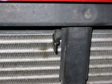
Note that the round openings do not cut into the reinforced area of the radiator support. I utilized an inexpensive air-body saw from Harbor Freight to cut the metal out and a 2-1/2” grinding wheel on a die grinder to contour them. This higher location causes the removal the material the lower of the two radiator support bolts attached on each side of the radiator. In this picture, the shiny dots above and towards the inside of the holes are the ¼” bolts I used to replace the displaced bolts.
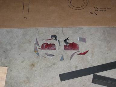
Very little metal had to be cut out of the radiator
support. None of the material removed
was from a double thickness (reinforced) section.
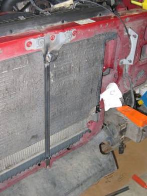
After relocating the bottom of the air conditioner condenser rearward using flat brackets in lieu of the factory ones, I welded up a straight brace to replace the original brace using a section of ¾” angle iron (The original brace had numerous bends and would have interfered with mounting the I/C in front of it.). I felt the angle iron would bear more loading in all directions than a piece of flat steel.
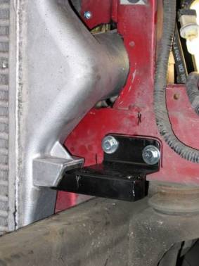
This picture shows the lower mounting brackets I fabricated. These consist of a section 2” angle iron, a section of 1” square tube (ends welded closed) and a piece of 3/16” steel added to the front of the square tube to make it match the width of the saddle on the intercooler. The forward-most surface of this bracket is 2-3/4” from the radiator support. This allowed room behind the I/C for the brace pictured above this photo.
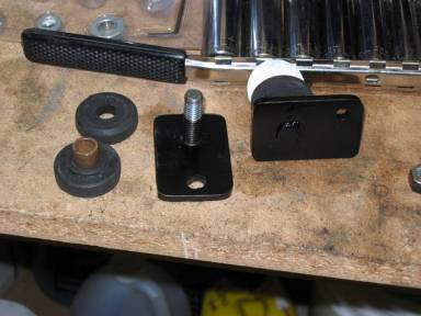
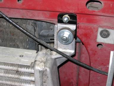
Here are close up and
installed photos of the upper mounting brackets. If you look closely at the “installed” picture, you can see that
the through bolt that secures the I/C to the bracket would contact the radiator
support if a bolt head were left on the back of the bracket. I tapped a hole in the bracket for the 3/8”
threaded portion of a carriage bolt.
Once threaded into the 3/16” plate, the head was cut off and the
remaining stud was welded to the back of the plate. The rubber isolators are cut from rear shock absorber bushings
from an ’84 Mustang and a 3/8” x ½” x 1” bronze bushing runs through the
center, secured by a fender washer, a lock washer, and a nut.
- Note that several of the attachment bolts in both
the upper and lower mounts are neither inline nor symmetrical due to
numerous sources of interference behind the radiator support. Check to see what is behind before
drilling!
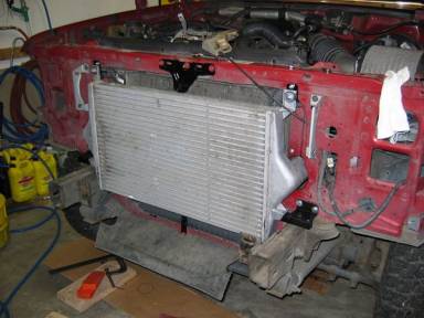
The two photos above show the I/C in it final location, secured in its mounts. While it did not require any modification to the black support structure or the grill, the “higher” mounting location caused interference with the hood release lever. After bending the lever to exit forward of the I/C, a little “clearancing” was still necessary as illustrated in the photo below this text.
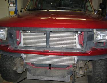
Here is the intercooler in its new home within the
reassembled front end.
Fabrication
of the Intercooler Pipes:
As mentioned above, I
utilized parts of the factory Super Duty pipes and some mandrel bent exhaust
tubing. The benefit to using the
factory pipes (or at least the ends) and the factory silicon couplers is that
there is a raised ridge molded into the couplers that seats in a groove of the
same shape in the pipe. The clamps that
hold the coupler to the pipe locks the coupler’s ridge into the pipe’s groove
and prevents the coupler from slipping off the pipe under boost pressure.
The factory pipes (99 – 03
7.3L PSD) are not a direct fit in the 94-97 trucks. Because the I/C is secured to the body and the engine is allowed
to move on its mounts, the factory couplers at the intercooler inlet and outlet
are of a “bellows” design that allows for the engine’s movement. Additionally, care must be taken in the
design and routing of the pipes to prevent rubbing on other parts. Several people have managed to make the
factory pipes “sorta” fit but have ended up with holes rubbing through the
pipes from the movement.
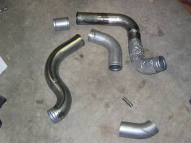
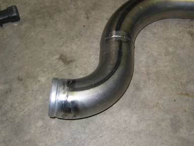
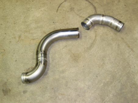
Above left - This is the final configuration I came up
with. The elbow in the bottom right
corner of the photo is a leftover part that should have been kicked aside
before taking this photo. The ends that
connect to the Y-pipe and the ends that connect to the intercooler are sections
from the factory pipes and can be identified by the grooves/recesses that
accommodate the ridges within the factory couplers.
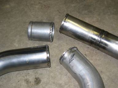
Above center - To prevent the two sections of each pipe from separating where a “straight” silicon coupler will be clamped, I welded a ring of 3/32” welding rod around each pipe end. The coupler slides over the ring and the clamp installs on the coupler “behind” the ring thus the clamped coupler cannot slide off the end of the pipe. Since the actual sealing occurs under the band clamps, the ring and its rough welds do not compromise the seal but do retain the coupler and clamp on the pipe. (My buddy/welding consultant suggested this method, thanks Jason!)
Here is a close up of the
last 1-1/2” of a factory pipe welded onto a 90-degree section of 18-gauge
exhaust tubing. This allowed the use of
the factory coupler at the intercooler.
Weldor’s note: The material on outer radius of the Hooker 18-gauge exhaust bend gets stretched very thin, much thinner than the rest of the pipe. Therefore it is easy to burn through when MIG welding it. I found that a lower wire-feed speed and a faster zigzag weld pattern minimized burn through and subsequent hole repairs. I deliberately chose 18-gauge tubing, believing it would be lighter and easier to weld 18-gauge tubing to the 20-gauge factory pipes. In retrospect, it would probably have been easier to weld 16-gauge pipe to the factory pipes. Interestingly, the factory pipes are bent in a way that preserves the thickness throughout.
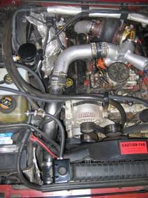
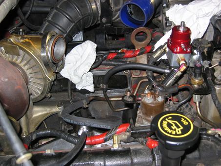
Above left - Here is the passenger or cold side pipe in its
installed position. Cables and hoses
were tie wrapped or rerouted to prevent rubbing on the I/C pipe. Note that I overlooked access to the oil
fill cap. It can still be used, though
a funnel is necessary. If I had routed
this pipe closer to the fender before turning towards the front of the truck, a
Super Duty Oil filler extension pipe could have been used. I used this particular bend simply because
it was an existing piece of one of the factory pipes, with a grooved end to
mate with the factory coupler at the Y-pipe (It was the I/C end of the factory
cold-side pipe). In the end, I think I
did OK as I have unrestricted access to the dipstick (which I use far more
often than the oil filler), and I normally use a funnel when filling the
crankcase with oil anyway. I have heard
that other installations severely restrict access to the dipstick.
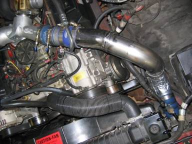
Above right - The photo shows the hot or driver’s side pipe
installed. The foil wrapped insulation
on the lower part of this pipe is a factory pipe section. The factory installed SD pipe has that
insulation over its entire length. Also
note the severely bent a/c line that runs between the compressor and the
condenser. Had Ford made the hose
assembly an inch or two longer, it could have gently been bent to go to the
fender side of the I/C pipe. If this
a/c hose fails due to the excessive bend I gave it, I will have an a/c shop
fabricate a custom assembly with a longer section of hose to go around the I/C
pipe.
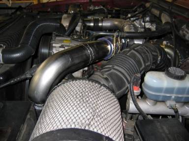
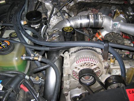
Here is the installed hot side pipe relative to the open-element intake.
Crank
Case Ventilation (CCV) Modification:
The CCV mod is done to
prevent oil vapor from the crankcase from entering the intake and being forced
through the I/C. The factory CCV
configuration vents the crankcase into the inlet of the turbocharger, and thus
into the I/C. When the interior of the
I/C gets coated with oil, the oil becomes an additional medium that the heat
must transfer through before it can reach the I/C’s aluminum core and dissipate
into the flow of air, thus reducing the I/C’s effectiveness. It also makes a mess when it oozes from the
couplers. Additionally, many silicon
couplers (including the ones I purchased from hosetechniques.com) are not rated
for contact with oil.
I attached a section of ¾” heater hose to the valve cover breather (remounted 180 degrees from its original orientation) and ran it back to the tailpipe, where it is plumbed into the tailpipe through an emissions check valve (one-way flow valve). This valve is probably not necessary as I elected to install it in the tailpipe, where exhaust backpressure would be the least. Near the check valve, I used a reducer and went to 5/8” hose that fits the check valve’s hose fitting. The other end of the check valve (outlet end) is threaded with ½” NPT. I bought a ½” water pipe nipple (3 or 4” long), cut the threads off one end and, in a lathe, turned the last few inches of the O.D. down to ¾” (1/2” water pipe is about 7/8” O.D.). This allowed me to weld the nipple into a ¾” hole I drilled in the tailpipe. Prior to welding the nipple in, I cut the end of the nipple at 45 degrees; I then installed the nipple into the tailpipe at an additional 45 degrees. This left the opening of the nipple at 90 degrees to the exhaust flow. This would allow the venturi effect to assist in scavenging the crankcase, if enough exhaust flow is present (this is a design theory, I have no idea what is actually happening down there!)
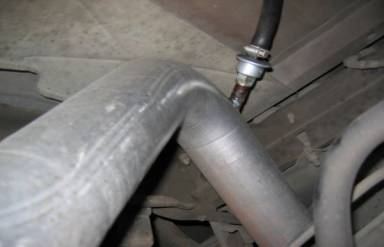
Pipe fitting and check valve installed in hump of tailpipe.
Theory Illustration.
Parts
list:
Ford parts:
Intercooler: YC35-6K775AC
(Each model year will have a different part#)
Early ’99 Y-pipe: F81Z-6K889BA
Clamp (Y-pipe to 94-97
compressor): F81Z-8287DA or M/craft
Service Part #YF-2488
Coupler (Y-pipe to 94-97’s 2”
intakes): F81Z-6C640FA (2-3/8” to 2”
reducer)
Clamp (I/C tube to I/C or
Y-pipe) 1C3Z-6K786BA (hot
side, floating bridge, constant torque – spring under nut)
Clamp (I/C tube to I/C or
Y-pipe) 1C3Z-6K786AA (cold
side, floating bridge)
HoseTechniques.com:
Silicon couplers: 3” dia. X
3” length x .140” thick, three-ply Aramid fiber reinforced (one black, one
blue, $11.00/ea.).
Hooker Headers (Summit
Racing part#):
U-bend: 18 ga. 6” radius: HOK-12280HKR
J-bend: 18 ga. 4” radius: HOK –12599HKR
Final
thoughts:
It is my sincere desire that
these photos and explanations will assist those interested in retrofitting a 99+
I/C into an earlier model truck. Dale
at TYMAR Performance provided consultation and shipped me a Diesel Power “race
burn” chip to go along with this install.
(I must mention that Dale feels very strongly that there are much more
cost effective way to deal with high EGT’s, when using stock injectors, than
stepping to an intercooler. Nonetheless
he was more than willing to work with me on what I want to do to my
truck.) The reduction in EGT’s from the
I/C should permit me to tow our 27’ travel trailer with the “race” chip. With the chip installed the truck pulls
wonderfully! The chip provided me not
only with A LOT more responsiveness and power throughout the rpm range, but
also extended the useful rpm range by 400-500 rpm. My experience with the stock programming and with the SuperChips
Micro Tuner (SCMT #1705) was that the power rolled off above 3,100-3,200
rpm. With the DP chip, the engine spins
effortlessly past 3,500 rpm pulling HARD all the way! These mods were made to enhance the towing ability of the truck,
and my earliest observations, without a load, suggest that EGT’s will not be an
issue when towing. Only the actual
towing up the mountain passes with the trailer attached will reveal the true
effectiveness and balance of this combination.
I look forward to the next opportunity to hook the trailer on and go!
May God bless all who read
this page!
TC
October
2006 Update!
It has been almost two years
since this page was posted in December 2004 and several changes and
observations have been made that I thought some of you might find
interesting. Let me start by saying
that the I/C works well. I have not
encountered EGTs much over 1,200 degrees even with several chip changes and the
addition of 130cc injectors from Dale I.
Since the injectors came from Bean’s place in Tennessee, it is safe to
say that they are what he sells at “Tranny Savers.” The performance increase from stepping up to these small (by
today’s standards) injectors is incredible!
The saying; “If you want to play, you’ve got to pay” held true in my
case… gradually the truck developed a chugging or hesitation at lower rpms
(1,800-2,000) when heavily load. After
having spent the better part of a year troubleshooting this, I discovered that
my fuel pressure under acceleration was falling below 30 psi and close to zero
with the fuel pump pulsations! This
condition led me to the Electric Fuel Pump Installation I will be describing
later on this page.
The changes my I/C
installation has undergone include a modification of the cold-side pipe to
allow access to the oil fill in the valve cover and use of the Super Duty oil
fill extension tube and then pressure testing the installation with compressed
air locate and then repair leaks.

Above left: These are the old and new upper sections of the cold
side pipe. The original installation
utilized a single existing bend from a factory SD pipe pictured on the
bottom. Above it is the new piece
fabricated from a few smaller sections of pipe.
Above right: To obtain
proper alignment with the revised upper pipe, the lower pipe was cut and
re-clocked.
Above left: This photo shows both the revised cold-side pipe and the SD filler extension installed. The original oil cap was reused. I do not have the Ford part # handy for the extension pipe but I ordered the part for a 2001 PSD. The extension came with a new o-ring on the base to seal against the valve cover. I have seen the 6.0 Liter extension used also, it is about an inch longer than the one shown here, so you can’t really get a wrong part that will not fit!
Above right: This is a
pressure adaptor or “plug” I made to pressurize the intake tract so I could
spray soapy water on all joints and locate any leaks. The white plastic piece was a 4” sewer pipe plug. I drilled the appropriate size hole and
tapped it ¼” NPT and installed the air fitting. The O.D. of the white piece was a bit larger than 4” but I was
still able to make it fit into the factory rubber intake hose that connects to
the CCV adaptor. It doesn’t make much
sense but their must not be any valve overlap as you can pressurize the entire
intake tract, including the compressor!
At about 16 psi, I was able to locate a few porous welds in my pipes and
a few couplers that needed to be a little tighter. I tried pressuring to 20 psi, but thought I must have blown the
oil pan off the truck by the sound I heard when the adaptor blew out of the
intake hose! I believe that tightening
the clamp a bit more would have held the adaptor in at 20 psi or more but my
heart rate hadn’t settled back down yet when I was re-pressurizing the
system! While I had the pipes out to
repair leaks, I painted them with Ford gray engine enamel to stop the surface
rust that was starting to appear.
Pictures in the fuel system section below contain a photo of the painted
pipes installed.
Electric Fuel Pump
Installation:
As mentioned in my
Intercooler Installation page, the addition of 130cc injectors created a fuel
delivery issue with my factory pump.
Ironic or not, I replaced the first factory pump at 54,000 miles and the
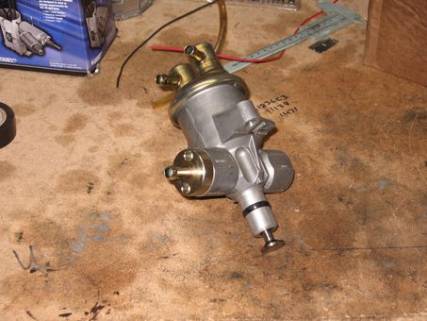
truck now has 109,000? For those of you
who are not familiar with the factory pump, it is a two-stage pump that has a
conventional diaphragm-actuated lift pump to bring fuel to the filter housing
under low pressure and a second piston actuated stage that supplies fuel at
higher pressure (40-60 psi) to the fuel rails in the heads, all driven by a
lobe on the camshaft and conveniently hidden in the bottom of the V-8’s valley.
In much the same way as I
conceived my intercooler project, I studied the information that was out there
on the internet and viewed a number of good write-ups on TheDieselStop.com and
other related sites, and gleaned what I felt were the best ideas from each.
Like many of the other
systems, I removed the entire stock filter/regulator/water separator housing
and replaced it with the Aeromotive fuel pressure regulator, frame-mounted
filters, and used a frame-mounted electric pump designed for a Super Duty. After being outbid on E-bay on several Super
Duty pumps, I ordered a Carter stock replacement pump for a Powerstroke in a
Super Duty application from Rock Auto for $168.00. If you run a Google search
on “Carter 74221,” you should find an interesting Tech Bulletin, albeit written
by Carter, explaining that all other pumps use the same brush (carbon) and
commutator (copper) material on their diesel pumps as on gasoline pumps. Carter claims that they are the only ones
who use carbon brushes and a carbon commutator to prevent premature failure due
to exposure to diesel??? I have had
great luck with other Carter products so I bought theirs, which does not come
with a mounting bracket. I went to my local
wrecking yard and pulled a mounting bracket and some 5/16” Ford Push-Lock fuel
fitting from a 1988 Econoline van.
Where my installation differs
from most others is that I elected not to replace the factory metal lines that
feed the fuel galleries through the rear of each head. I did this for two reasons. First, as this is my family RV hauler and
not a race truck, the 130cc injectors will not likely ever be replaced with
anything larger so I don’t believe those lines create a significant restriction
in this application. Finally, these lines
are required to run in very close proximity of the turbo housing and exhaust
downpipe. The cautious side of me said
that I didn’t know the temperature limits of the commonly available fuel hoses
and testing those limits under load, on a long mountain pass, with sustained
1,200+ degree exhaust temps, and the family onboard was not something I wanted
to try! I am not questioning the
judgment of those who have replaced the metal lines in their installations, I
am just saying that for the above reasons, I elected to retain the metal
lines.
In The
Engine Compartment:
The first challenge to tackle
was how to tie a 3/8” fuel hose to the banjo-bolt fitting on the metal
lines. Since a picture is worth a
thousand words, or so they say, I think you will be able to see where I am going
with this.
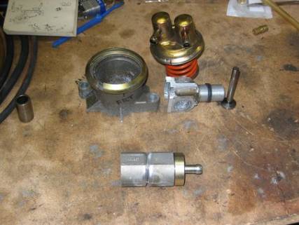
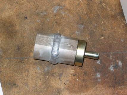
If you guessed that I would
then have the inlet and outlets of the cut up pump TIG welded together, you are
correct. Since my welding equipment and
experience does not include the ability to weld aluminum, I had they job done
at a local welding shop. The result can
be seen below:
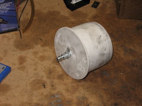
Fuel pump removal:
I removed the factory fuel
pump (the pump that was cut up to make the adaptor pictured above was one that
I had previously replaced) without removing the turbocharger. This method has been discussed many times on
TheDieselStop.com with some people custom bending 1-1/4” wrenches to clear the
turbo pedestal, while others have done some creative grinding on the pedestal’s
webbing to give wrench access to the banjo bolt. I purchased a cheap ($14.95, but nicely finished in chrome) set
of large combo wrenches from Harbor Freight and was prepared bend, twist, and
mutilate one do this job. As it turned
out, the banjo bolt in its tightened position was perfectly placed so I could
break it loose by simply placing the box-end of the wrench on it and
pulling! With the engine positioned so
the cam lobe was pushing the pump up in it’s bore, I carefully lifted it out
without disturbing the tappet. No
drama, no lost tappet. The factory fuel
filter/water separator housing was removed in the course of pulling the pump,
never to be reinstalled.
Plugging the fuel pump
hole:
Since I would not be
replacing the mechanical pump, I set out to find a freeze plug to fill the
hole. Several people said that they
used a 7/8” freeze plug. I contacted
Ford and they wanted $9.00 to order the correct freeze plug, the parts computer
described it as a .892” plug. I assumed
that a plug for 7/8” (.875”) hole had to be larger than the hole so there would
be a friction fit. I purchased a 7/8”
freeze plug for $0.49 at NAPA and it measured right at .888.” In the name of caution, I took a small punch
and dimpled the freeze plug outward in four places before installing it, to
make it a tighter fit. I coated the
dimpled plug with Permatex #2 and drove the plug in using a socket that was too
larger to drive the plug through the hole and into the crankcase! Done deal.
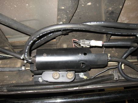
Above: In this photo
you can see the adaptor bolted in the place of the fuel pump with the banjo
bolt. Across the top of the adaptor is
a piece of ¾” angle iron that bridges the two fuel pump mounting pads on the
block and is bolted down on the driver’s side.
This angle iron was then used as a brace to strap the adaptor to, to
prevent movement and vibration that could possibly fatigue the joints on the
metal line. Sorry about the picture
quality but my little Canon digital didn’t want to focus down at the bottom of
the valley!
Routing the fuel lines:
Again, I will remind the
reader that this is not intended to be an all out performance system, just a
reliable one that supplies sufficient fuel volume and pressure utilizing an
electric fuel pump, so I did not upgrade to 3/8” lines from the tanks to the
heads. I utilized the 5/16” metal lines
on the frame that begin just ahead of the fuel tank selector valve and run up
to the engine. Once along side the
engine, Ford connects them to flexible, steel-braided, lines that run up the
motor and join with a 3/8” metal hard line for the feed, and a 5/16” for the
return line. With only slight bends to
the hard lines in the valley, I used 300 psi-rated fuel hose with a
fabric-braided jacket to connect the 3/8” hard line to the adaptor I made to
connect to the banjo fitting at the metal lines under the turbo. The following photo shows the routing I used
connected the 3/8” hard line to the adaptor.
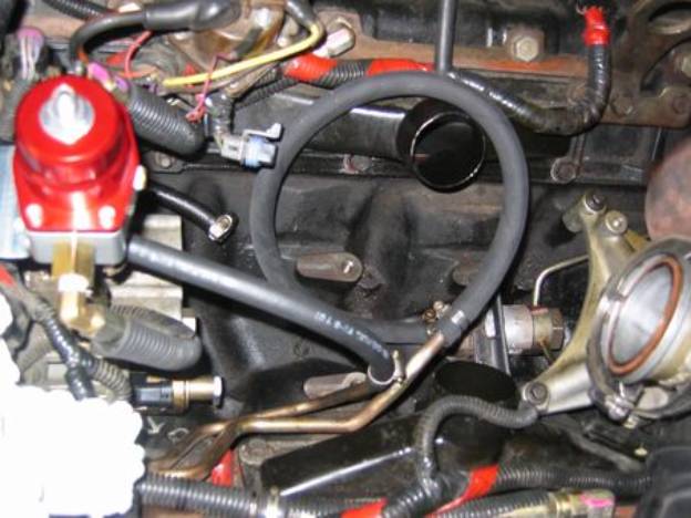
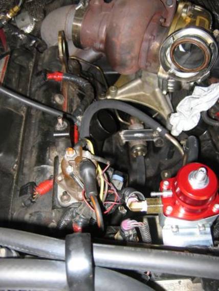
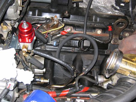
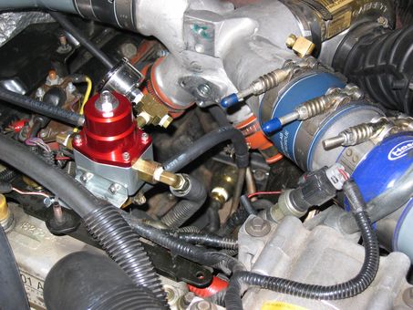
I mounted the Aeromotive regulator with its provided bracket to the metal brace that runs across the top of the HPOP reservoir. My local Parker hose dealer had the –6 SAE O-ring to 1/8” NPT adaptors that allowed me to connect the factory 90-degree fittings from the factory regulator to the Aeromotive regulator. The factory return lines from the front of each head were then connected to each side of the new regulator. On the bottom of the new regulator, a –6 SAE O-ring to ¼” NPT adaptor and a 90 degree fitting with hose barb end allowed me to use 5/16” line to connect the regulator outlet to the 5/16” return (hard line). The two photos below better show the routing of return lines coming into each side of the regulator as well as the outlet of the regulator connecting to the hard line.
Frame
Mounted Components:
To offer the components as
much protection from road debris and to allow the best access to my filters
(for filter changes) I decided to mount both filters on the frame behind the
T-case on a common bracket and mount the pump separately on the frame behind
(rearward of) the filters on its own bracket.
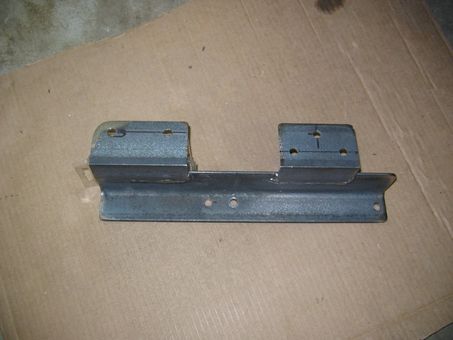
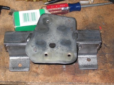
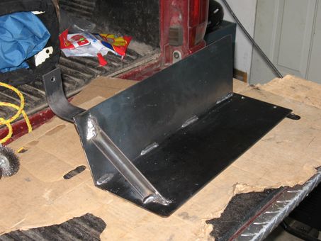
Above left: Filter bracket – simple construction, 1-1/2”x2” angle
iron welded and drilled in a configuration that allowed it to bolted to the
frame using existing holes.
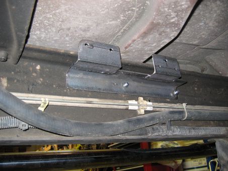
Above right: Filter bracket being test fit on frame.
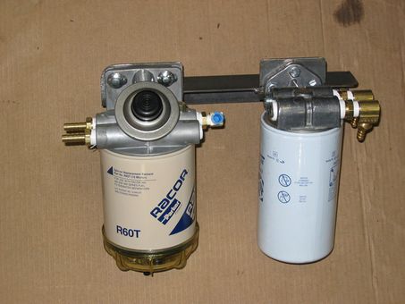
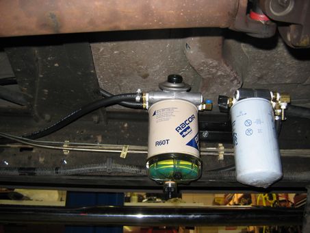
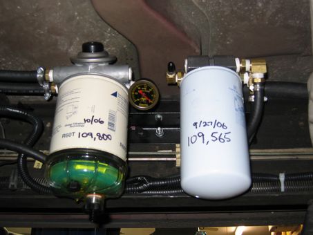
Above left: Filters being test fit on bracket. Above right: Filters mounted on
frame.
About the filters:
I have come to find that
Racor is THE trusted name in water separators in the marine industry, so
naturally I assumed I needed the best!
I used a Racor 460R10 filter/separator in a pre-pump (primary) configuration. The “460R10” breaks down to: the 400 series
filter head that has a built-in primer pump to prime the filter and pump out
water when you open the bowl drain, the 60 indicates a flow capacity of 60
gal/hr (Racor also makes a 445R which would likely have been more than adequate
– it differs only by size of the element used.), and the 10 indicates that it
has a 10-micron element. Elements are
available with 30, 10, and 2-micron ratings.
If the 10-micron element clogs before my 15,000 miles change interval, I
may change to the 30-micron unit and allow the secondary filter to do a little
more work.
For the post-pump (secondary)
filter, I took the advice of Tom S. on TheDieselStop.com and read up on CAT
(Caterpillar) filters. CAT was among
the first to introduce the HEUI injectors in their Over-The-Road trucks and
they claim that their 2-micron High Efficiency Fuel Filters are crucial to
protecting the small components in HEUI injectors from abrasion and wear. Through the WIX Filters website, I was able to
confirm that their replacement for the CAT 1R-0750, the WIX 33528/NAPA Gold
3528 is, in fact, a 2-micron element designed for CAT applications. I purchased both a WIX filter head and
several 3528 filters from FleetFilter.com.
The filter head cost $15.40 or so and the filters were about
$6.30/ea. Locally the same WIX filter
head was $34.00 and they would have had to order one in and I believe the CAT
filters run about $14/ea. I will
probably buy the CAT filters in the future, but since I was placing an order
for the head, and because I trust the quality of WIX filters, I tried them this
time.
Subsequent conversation with
Dale I. revealed that Parker, Racor’s parent company, claims the Ford factory
element, made by Racor, is a 5-6 micron element. However, Dale’s conversation with them left him convinced that
Racor is not rating their filters by the same standards that others do. When CAT says 2 micron, it means that 98% of
particles 2 microns or larger are stopped by the filter.
Plumbing the filters:
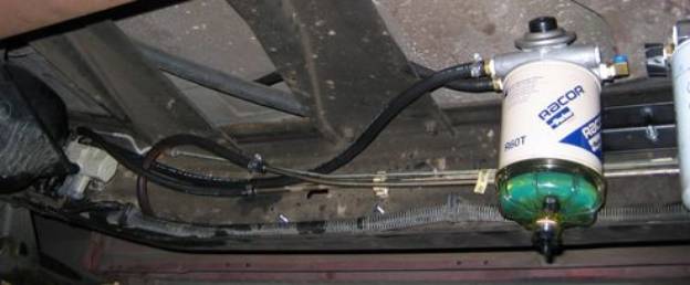
In the following photo, taken before the fuel pump was mounted, you can see the fuel tank selector valve (has a white housing, and is mounted on the frame just a head of the fuel tank) that switches the feed and return lines between the front and rear tanks. Of the two hoses that come from the top of the selector, the one closest to the frame is the “outlet” of the selector and is the feed line to the engine and can be seen running to the inlet of the Racor 460. (The other hose on the selector valve is the return line and is left unaltered.) The hose on the outlet of the Racor is draped over the frame because gravity was beginning to fill the Racor so I didn’t want a hanging hose to draw all my fuel out on to the floor! That hose will eventually go to the inlet of the fuel pump.
Now move your attention to the two metal lines that meet up with the black fuel hose about a foot ahead of the selector valve. Disregard the third, smaller hardline, it is the rear brake line. Of the two larger (5/16”) hardlines, the one that has been bent upward slightly was formerly connected to the selector valve’s outlet, as it runs forward up to the motor. I bent this line upward to accommodate a larger bend radius for the hose coming to it from the outlet of my secondary filter. Essentially I am splicing two filters and a fuel pump between the selector valve’s outlet and the end of the bent hardline.
Mounting the Electric Fuel Pump:
Above left: This is the mount I fabricated to allow the electric
fuel pump bracket from the 1988 Econoline van to be bolted to the frame. Note that the lower holes in the bracket are
drilled at different heights on the angle iron. This allowed the mount to be bolted to the frame using existing
holes in the frame. I did not drill a
single hole in the frame during this installation.
Above right: This photo shows the Carter fuel pump mounted
(hidden) in its bracket with the fuel lines attached.
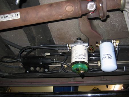
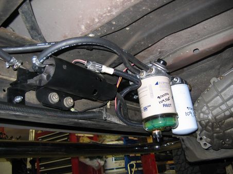
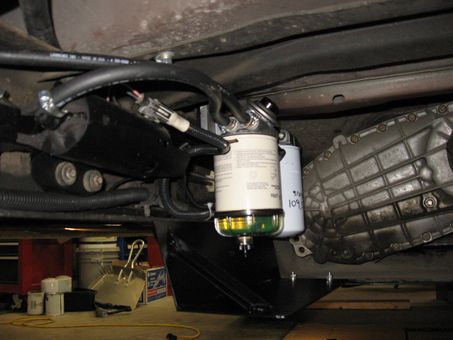
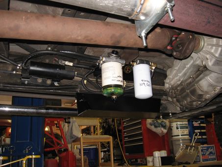
Above left and right: A couple
different angles on the under-vehicle installation. Note that outlet of the Racor filter is connected to the inlet
(rear) of the pump with a 90-degree fitting.
The outlet of the pump has a straight fitting attached to the hose that
runs to the inlet of the 2-micron WIX filter.
To summarize the new path of the fuel; it leaves the selector valve via
a hose to the inlet of the Racor filter/water separator, it leaves the Racor
and goes to the inlet of the electric fuel pump. Up to this point the fuel is drawn under suction to the
pump. The fuel leaves the pump under
pressure and runs through the secondary filter and is connected up with the
frame-mounted hardline that runs up to the motor.
Other details:
Since the Carter pump was a direct
replacement for the Super Duty, it was designed for the 5/16” Ford Push-Lock
connectors on both the inlet and outlet.
Because we travel far from home with this vehicle, my installation used
the Ford fittings so any stock replacement pump could be installed should a
pump failure occur. As mentioned above,
fuel is pulled through the Racor filter under vacuum, therefore a vacuum gauge
mounted on the outlet of the Racor allows me to monitor the condition of the filter. The new filter requires about 3 inches of
vacuum to pull the fuel through.
Literature indicates that a filter change is due when the reading
reaches 6 to 10 inches(/Hg.).
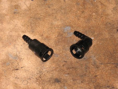
Above left: Straight and 90-degree Push-Lock fittings. When installed, the fittings use a white
plastic horseshoe shaped retaining clip to hold the fitting on the hard line or
pump.
Above right: a closer view of the vacuum gauge installed on the
Racor filter/separator.
Power is supplied to the pump
via a relay and 12ga. wire. I used a
Ford fuel pump relay from a late model Mustang that I parted out years ago,
again staying with parts that should be readily available should we need parts
along the way somewhere. As I type this
I realize that the Bosch-style, #85, #86, #30, #87, 30-amp relay is probably
more readily available…
To keep the pump from running
if the ignition is on but the engine is not running, the “ignition on” wire
that triggers the relay is run through an oil pressure switch that closes when
oil pressure is present. The Holley
pressure switch is a SPDT switch that allows power from the starter circuit to
trigger the pump on when the starter is engaged, but when oil pressure develops
the ignition-on wire takes over and keeps the pump powered. The schematic for the use of this pressure
switch is readily available for viewing on the Holley website. Simply select the part by number and when
you are viewing the information page for the part (Part #12-810), there will be
a button to download the schematic. I
had temporarily wired the pump to run whenever the ignition was on, to test the
system, and it was quite annoying.
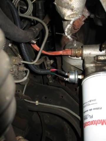
Above: The switch can be seen in this picture just above and
to the left of the oil filter, attached to the rear oil cooler header. If you use this switch, you will need a short
pipe nipple and union to space the switch away from the header so the body of
the switch can clear the aluminum webbing that can be seen above the
switch. The switch has a 1/8” NPT
fitting and is installed in place of a 1/8” NPT plug that Ford was nice enough
to put in the oil gallery of the header.
Button
It Up - Fire It Up!
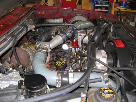
The two photos above give a
view of engine compartment after everything was reassembled. Notice the 3/16” black hose running from the
upper half of the Aeromotive regulator up towards the radiator. This hose is connected to the ‘boost
reference” port of the regulator which is designed to allow the regulator to
increase fuel pressure as boost pressure increases (at 1:1 ratio) when connected
to a boost source (our intake tract), and reduce fuel pressure under vacuum on
gasser applications. While the idea of
increasing fuel pressure when the Powerstroke is under load sounds like a good
idea and may provide a performance advantage, an understanding of how the
regulator works will explain why I did not.
The boost pressure from the small hose acts upon a diaphragm inside the
regulator. The motion from the
diaphragm moves internal parts that raise the fuel pressure. The diaphragm also separates the dry-side of
the regulator from the wet/fuel side of the regulator. Therefore, if the
diaphragm fails, pressurized fuel will come through the diaphragm and into the
intake of the engine via the boost hose, potentially creating a runaway
engine. Basic diesel theory explains
how an uncontrolled flow of diesel into the engine can cause the rpm to climb
until nature and/or physics causes the engine to fail from excessive rpm! Therefore, the small hose you see pictured
runs through the radiator support and points down to the ground. When time allows, that hose will be directed
below the truck, behind the motor, and away from the hot exhaust system.
No project of this magnitude
seems to go without at least one glitch.
In this case the custom adaptor I had welded up to allow me to connect
the 3/8” feed hose to the banjo-bolt fitting and metal lines leaked at the weld
seam. I took it back to the welding
shop that did my TIG welding for me and they indicated that the diesel oil that
had saturated the part prior the welding job, causes vapor pockets or pores
when welded as the diesel vaporizes and pops.
They apologized and cut the joint apart and re-welded, ground the weld
down, and re-welded the joint three times before the welder was satisfied that
the weld was leak-proof. No charge for
the rework and big time apologies.
It wasn’t until I got the
part home and was going to reinstall it that I realized that they had clamped
the part in a vice several times, with the vice jaws on the front and rear
sealing surfaces of the part. Essentially
they destroyed the surfaces that the banjo-bolt washers seal against.
Out of desperation, I went to
the Parker hose shop and asked how I might be able to adapt a 3/8” hose to this
unique fitting that the banjo-bolt attaches to. “What Unique Fitting?
That looks like a standard ¾” SAE O-ring seal fitting.” It turns out that it is, only Ford chose to
use sealing washers on the flat end surfaces instead of o-rings. Due to the design of an SAE O-ring seal
fitting, the end surfaces are machined flat anyway as this is where the parts
tighten against each other (though the o-ring does the sealing). The flat end surface of the Parker fitting
made for a perfect seal using the banjo-washers!


Above left: Custom, clever-designed, professionally welded, expensive,
and leaky part.
Above right: Twelve dollars worth of leak-free Parker
fittings. In this photo, assembled from
left to right are; 1) –12 SAE O-ring to ¾” Male NPT adaptor, 2) ¾” NPT Female
to ½” NPT Female adaptor, and 3) ½” NPT to 3/8’ hose barb adaptor. If you look closely at the right hand
picture immediately above this pair of photos, you can see this part installed
in the bottom of the valley. Look for
the anodized finish and the white Teflon tape between the sections.
Protecting
the frame-mounted filters from road hazards and debris:
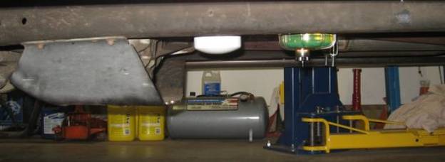
After I had the system fully
operational, I figured the odds of a front tire tossing up a rock or solid
object and striking one of the filters, more specifically, striking the plastic
bowl on the bottom of the Racor, were about one in a million. Being that I am a one-in-a-million kind of
guy and since one bad rock can ruin your day, I picked up some 1/8”x6” flat
stock and fabricated the shield you see below in the side views of the truck
both before and after installing the shield.
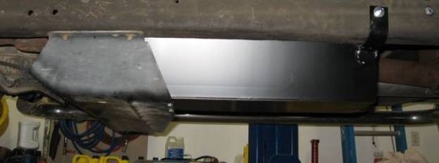
Below: If your truck has the t-case skid plate that mine does (part of the Off-Road Package?), you will recognize the forward angle on the side of the shield corresponds with the angle of the factory shield. I intended to run a brace from the right rear of the shield up to the frame cross member above but the unit seemed pretty solid with just the left rear brace bolted to the frame (existing hole, of course), so I decided on a compromise and ran the diagonal brace at the rear of the shield. Recall that this a shield and not a skid-plate!

Part Numbers and
Specifications:
Aeromotive Regulator: Part# 13109
(Summit Racing).
Aeromotive 1-1/2” pressure
gauge: Part# 15633 (Summit)
Holley Oil Pressure Safety
Switch Part# 12-810 (Summit)
Carter Electric Fuel Pump: Part#
74221 (Factory replacement for 7.3L PSD equipped Super Duty – Rock Auto).
Racor Water Separator/Filter: Part# 460R10 – built-in
primer pump, 60 gph capacity, 10-micron element (E-bay).
Secondary Filter Header
(WIX): Part# 24770
(Fleetfilter.com).
Secondary Filter – WIX/NAPA
Gold: Part# 3528 NAPA or #33528
WIX (Fleetfilter.com). You can use CAT
1R-0750 also.
Marshall 1-1/2” vacuum gauge: Part# 8135 (E-bay).
Fuel hose – 3/8” Aeroquip
300 psi rated, black with fabric braided jacket (Local hose shop).
Fuel hose – 5/16” Suction
side – Trident A1 rated marine fuel hose (Local hose shop).
Pressure
side – Goodyear High Pressure Fuel Injection hose (Autozone).
Parker fittings and adaptors: Too many to list part
numbers. (Local Parker Dealer)
Freeze plug (seals fuel pump
hole): 7/8” dimpled for firmer
fit.
Fuel Pump Relay: Ford –
OE on ’87-’93 5.0L Mustang.
Closing
Comments:
There is an overall
smoothness to the way the engine runs and idles with an electric pump. I have only had the system up and running a
few weeks but it seems to work well. I
will have a chance to tow in another week and see how loaded performance is
affected by the new fuel system. As
with the Intercooler page, it is my hope that this information will be useful
to those who are considering what would be involved in fabricating your own
system. With any luck this info will
save you a few glitches along the way!
I welcome any comments,
questions, or feedback. My e-mail is
listed below and I can be reached by Private Message (PM) on TheDieselStop.com
at TimC63.
Good luck and God Bless,
TC